Illustrated Anatomy of a Conn Valve, 1930s - 1940s
Part 1: Components
Introduction
I have been looking into the construction of the Conn valve from the 1930's and 1940's, specifically in relation
to vertical alignment, and have learned a lot. I will try to share what I have learned in two articles. These article apply
specifically to the bottom spring type of valve used on Conn cornets and trumpets with serial numbers starting with 3xx,xxx,
but it should apply equally to other Conn valves instruments from that period. I haven't (yet?) had the opportunity
to disassemble a Conn valve with a 2xx,xxx serial or a 4xx,xxx serial so I don't know to what extent those are
different. I do know that valves on 6A/6B and 10A/10B Victor models with serials 6xx,xxx and 22B Victors through at least serials
Cxx,xxx are very similar to what is described below. That means that presumably all Victor models with bottom spring valves fall
into the category of this article. Director models have different (simpler) valves.
This first article deals with the components of these valves. Part two discusses vertical alignment.
Disassembling the valve
When you unscrew the top valve cap and remove the valve you will see a valve similar to this one:
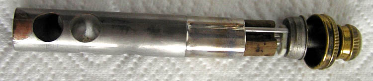
As you can see the bottom of the valve shows some corrosion, but that isn't relevant to us here.
The first step in disassembling a valve is easiest to do before entirely removing the valve from the valve casing. Before completely unscrewing the top valve cap, give the finger button a single (!) twist counter clockwise as seen from above, just enough to loosen it (don't completely unscrew it yet). The reason for doing this is that the valve guide stops the valve from rotating in the valve casing, making it easier to unscrew this. One of two things will happen when you do this: a) the finger button will unscrew from the valve stem or b) the finger button and valve stem will both unscrew from the valve body. While the finger button, valve stem and valve body are all separate parts, in my experience either the finger button is so tight on the valve stem that unscrewing the finger button will unscrew the valve stem from the valve, or the valve stem is so tight on the valve body that it won't unscrew and you unscrew the finger button. Whatever you do, don't force anything.
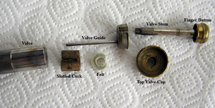
After you do this, unscrew the top valve cap and remove the valve (remember, the finger button and/or valve stem are still loosely screwed in to the valve). You can then proceed to gently slide all the other parts off the valve stem, leaving you with a set of parts as in the picture below. As you can see in this case the finger button didn't unscrew from the valve stem; the valve stem unscrewed from the body of the valve. It is equally likely that your finger button will unscrew, leaving you with a separate finger button and a valve body plus valve stem. This may well vary from one valve to the next on the same instrument.
Valve Body
When looking at the top of the valve body, you will see several things:
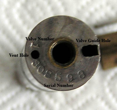
a) The serial number of the instrument the valve came from. If this serial number doesn't match the serial number on the
second valve casing, the valve is originally from a different instrument.
b) The valve number. As you can see in the picture, this particular valve is the first valve. This prevents you from
getting the valves mixed up.
c) The vent hole. Valves are hollow, and I presume this hole is to prevent pressure differences between the inside and the
outside of the valve.
d) The valve guide hole. This is the hole the valve guide goes into. Don't insert the valve guide into the vent hole, the valve
will be reversed in its casing.
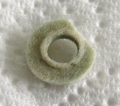
Slotted Cork
Next we come to the slotted cork. Although the picture below doesn't actually show the slot (see the first or second
picture in this article), it does show the angled edge of the cork.
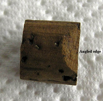
The slot along the length of the cork is to make sure the cork doesn't obstruct the valve guide. When reassembling the valve, remember to insert the valve guide along the slot in the cork. The angled edge of the cork, opposite the slot, is there so the cork doesn't block the valve body's vent hole. When reassembling the valve, remember to position the cork so this angled edge is down, against the valve body and above the valve's vent hole.
These slotted corks can eventually wear out, crack, etc. Sometimes you will find a valve with replacement cork fashioned from a wine bottle cork. Often such a valve will be significantly off in vertical alignment. Replacement slotted corks can still be obtained. Contact me for an address where you can buy some (e-mail is on main page of this website). The corks are 0.5" diameter. When you get your replacement cork you will have to cut it to the right length. The length of the slotted cork varies from one model to the next, so don't rely on measurements from one model's slotted cork to work equally well on another model. The best thing to do is to measure the cork on a valve from the same instrument which is in the best, preferably original, condition. If this isn't possible, do measure cork on another instrument of the same model.
I have measured the corks of the three instruments I have here at home that fall into the time period covered by this article. I find it is difficult to measure these corks accurately even with a digital caliper, because even if the corks were originally cut accurately, over the years they may have compressed, cracked or otherwise been bent out of shape. Here is a short table of measurements:
| Conn valve cork lengths | ||||
| Model Number | Year built | Cork length decimal inches |
Cork length fraction inches |
Cork length metric millimeters |
|---|---|---|---|---|
| 38A | 1936 | 0.500 ~ 0.510" | 32/64" ~ 33/64" | 12.7mm ~ 12.95mm |
| 22B Special | 1936 | 0.5625" | 9/16" | 14.29mm |
| 12B | 1938 | 0.5625" | 9/16" | 14.29mm |
| 22B | 1941 | 0.5625" | 9/16" | 14.29mm |
| 22B | 1948 | 0.577" ~ 0.583" | 37/64" | 14.65mm ~ 14.80mm |
With respect to this table I am surprised that the length of cork on the 12B and the 22B are different for being essentially the same instrument. Nevertheless, with these lengths and the same felts the valve height is good. It seems to me that being U.S. built instruments from the 1930's and 1940's the corks ought to be some fraction of inches. For the 12B this is true: 9/16". Either way, I repeat the advice: measure a good cork on the same instrument. And if in doubt, leave the cork a bit long since you can always shorten the cork a bit. You can't make a cork longer once it has been cut.
Original corks are usually easy to distinguish from replacements: the originals have turned dark like the one on this picture, replacements are much lighter in color. A tip on cutting replacement cork to length: use a VERY sharp (so be VERY careful! Don't even THINK about doing this if you aren't an adult!) single edged razor. Apparently these replacement corks sometimes tend to crumble if you use a knife that isn't sharp enough. After you have cut the replacement cork to the right length, you will need to cut an angled edge. I find it best to do this on the opposite side from where you have cut the cork to length. The reason for this is that the cut side is likely to be not perfectly smooth. This is OK because it will be covered by a felt. The opposite side will be smooth, making this the better side to sit against the valve body. Cut the angled edge on the smooth end.
Felt
On top of the slotted cork sits a piece of felt. The felt serves two purposes: 1) to muffle the sound of the valve hitting the
cork as the valve comes up 2) to adjust the vertical alignment of the valve when it is in the "up" position. These felts are the
same diameter as the slotted corks, 0.5". Most of the old, original looking, felts I see appear to be 1/32" thick ((0.794mm). However,
with this most valves are also slightly high. I have received some new felts that 1/16" thick and these appear to work very well. If you
use felts that are between 16/32" and 17/32" in diameter with a hole of 3/16" and either 1/16" or 1/32" thick you should be OK. Allied Music
Supply has felts under part number A412 which fit the bill nicely. The felts under the finger buttons need to be no larger than 16/32" in
diameter; 17/32" won't fit without trimming. This means the A412 felts which are 17/32" will need to be trimmed to be used under the finger
buttons. To allow for free movement of the stem of the valve guide, the felts should either
have the hole in the middle be off-center, or should have a wedge or section cut off. If not, the valve guide stem will rub against
the felt making it more difficult to insert the valve easily into the valve casing (specifically, the valve guide won't comfortably
fit inside the valve casing), and obstructing the easy vertical movement of
the valve. I believe original Conn felts are red. I know for a fact that the one pictured here is a replacement felt.
These felts are essential in the vertical alignment of the valve.
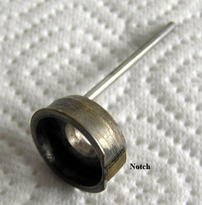
Valve Guide
The purpose of the valve guide is to take care of the rotational alignment of the valve; in other words, to make sure
the holes on the valves line up with the tubes of the instrument from side to side. The stem on the valve guide inserts into
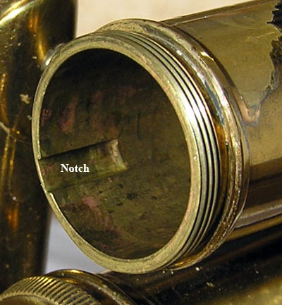
the valve guide hole on the valve body and sits in the slot of the slotted cork. The notch on the valve guide fits into
the notch on the valve casing when the valve is inserted into the valve casing. When correctly assembled these valves will
only fit into the valve casing one way. The design of these valve guides must be quite good, because I have never yet seen
a Conn valve of this type of which the rotational alignment was off.
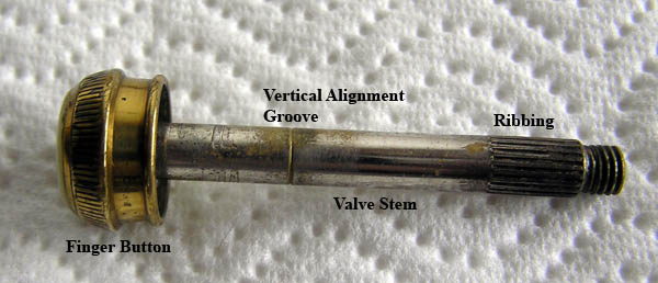
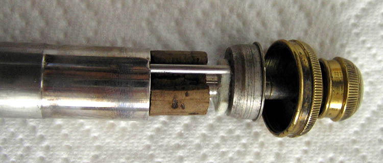
Valve Stem
The valve stem (pictured here with the finger button because on this valve it is too tight to be unscrewed) has some interesting features that might not be obvious
on first glance. First there is the ribbing along the bottom of the valve stem. This is intended to prevent the slotted cork
from rotating. Second, there is a groove around the valve stem. This is there to aid in evaluating and setting proper
vertical alignment of the valve. More about this in part two on vertical alignment.
Finger Button
As you can see in the pictures below, the underside of the finger button holds a piece of felt, underneath which is
a piece of cork. The felt is essentially loose in the finger button, the cork is glued in place. These felts are
the same diameter as the felts used on top of the slotted cork: 0.5".
The purpose of the finger button is obviously to make it more comfortable for the player to press the valve down.
However, the finger button, more specifically the felt under the finger button, is also a part of the vertical
alignment of the valve in the "down" position. More about that in part two on vertical alignment (Yes, this
is a finger button from a different valve on the same instrument).
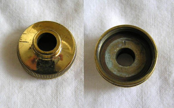
Top Valve Cap
Interestingly, the top valve caps are number on the underside (see picture). Why this is I don't know, since
as far as I am aware all three valve caps are identical and interchangeable. If you have problems with a valve sticking
you might try replacing the top valve cap.
And finally a close up picture of the (re-)assembled valve.
Springs
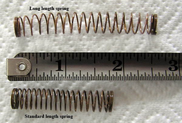
Original Conn bottom springs on instruments from the 1930's and 1940's are straight, and on cornets and trumpets
come, as far as I am aware, in two lengths. I call them "Standard Length" and "Long Length" springs. The standard
length springs are found on instruments such as the 12B and the 22B. The long length springs are found on Victor cornets
such as the 80A and the 38A that have a taller valve casing. See picture below. The tape measure in the picture is in inches. Multiply by 2.54
for centimeters.
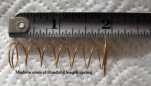
If you need to replace the standard length springs, you can get conical springs that work very well. One possible advantage of these springs is that they are slightly wider, resulting in the spring pressing up on a wider area of the bottom of the valve. The advantage of this is that it can reduce side to side pressure on the valve making it less liable to stick. If you have problems with a valve sticking a bit, especially while you are playing but not when you are simply "twidling" the valves without playing the instrument, you might try some of these conical springs. Contact me for an address where to get these conical springs (e-mail is on the main page of this website).
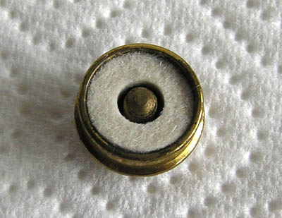
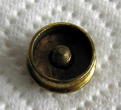
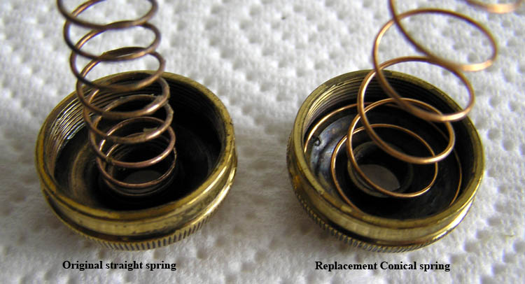
Original straight Conn springs attach to the bottom valve cap by being pressed over a small "stem" in the center. I find the easiest way to do this is to hold bottom valve cap in one hand and with the other hand hold the spring at one end. Gently put the other end of the spring against the "stem" at the center of the bottom valve cap. Compress the valve a little bit and turn the spring counter clockwise a little. The spring should slide right into position. Replacement conical springs sit along the inside edge of the bottom valve cap.
See part 2, Illustrated Anatomy of a Conn Valve, 1930s - 1940s, Part 2: Vertical Alignment, for a discussion of vertical valve alignment.
See part 3, Illustrated Anatomy of a Conn Valve, 1930s - 1940s, Part 3: Sticking Valves, for a way to tackle sticking valves.